|
 Locating water heating equipment on the roof of a high-rise helps increase its longevity, but it can be a challenge for the designer. Locating water heating equipment on the roof of a high-rise helps increase its longevity, but it can be a challenge for the designer.
PM Engineer Issue: 4/05
When natural gas is the preferred source of energy for domestic water heating in high-rise buildings, the static pressure of the proposed hot water distribution system will exceed the maximum relief valve pressure setting of 150 psi for the listed T&Ps required at the water heating equipment. Therefore, a rooftop location for the equipment offers many long-term economic and design benefits. With a rooftop location:
- Gas pipe is cheaper and smaller in diameter than flue pipe, returning square footage to the architectural floor plans and providing a construction cost savings.
- Longevity of the water heating equipment is increased by the reduction of the operating pressure at the equipment, from near 150 psi for a basement location to approximately 25 psi for a roof location.
Buildings that require multiple water pressure zones to limit useable water pressure at plumbing fixtures to the code-required maximums, and that also require circulated return systems from domestic hot water distribution risers, present a unique design challenge. The problem here is to “centralize” returns from zones with different pressures back to the water heating equipment at the roof. The solution mentioned in the Aug. ’04 PME article, “Design Considerations for Pressure Reducing Valve Stations In Domestic Water Systems,” has been shown to be effective in many working installations and has become the standard practice in many marketplaces for the mentioned design conditions.
Designers and engineers may enhance the effectiveness of this means of justifying the pressure differential between multiple distribution zones into a central riser, with thoughtful distribution system layouts that include:
Provisions for effective air removal at the top of each zone.
- Correct sizing of return pump and return piping to avoid velocity erosion in piping.
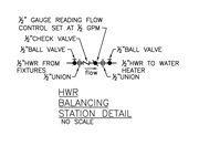
- Control of flow rates and direction with gauge-reading flow control devices and check valves at each connection of a return pipe to a hot water distribution riser.
- Location of the return pump on a nonresidential floor, preferably with other mechanical equipment, to conceal objectionable noise.
Air Relief
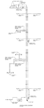 A major cause of poor performance in hot water return systems is “air binding,” caused when air released from the heated water rises and collects at the top of a zone. This reduces and
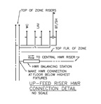
eventually prevents adequate return circulation flow rates from occurring. Distribution layouts that establish the connection of the return pipe to the hot water distribution riser at the floor below the highest plumbing fixtures allow air to bypass the return system connection to the riser. The air is then vented out of the plumbing fixtures above with each use of the fixtures. This arrangement has been shown to be much less problematic than systems where the return pipe is above the highest plumbing fixtures as a vertical extension of the hot water distribution riser. Layout of the hot water distribution system that establishes venting of trapped air through the plumbing fixtures above—whether up-feed, down-feed or up- and down-feed system configurations—can be the most important factor in avoiding balancing and adjustment problems during initial system commissioning. A major cause of poor performance in hot water return systems is “air binding,” caused when air released from the heated water rises and collects at the top of a zone. This reduces and
eventually prevents adequate return circulation flow rates from occurring. Distribution layouts that establish the connection of the return pipe to the hot water distribution riser at the floor below the highest plumbing fixtures allow air to bypass the return system connection to the riser. The air is then vented out of the plumbing fixtures above with each use of the fixtures. This arrangement has been shown to be much less problematic than systems where the return pipe is above the highest plumbing fixtures as a vertical extension of the hot water distribution riser. Layout of the hot water distribution system that establishes venting of trapped air through the plumbing fixtures above—whether up-feed, down-feed or up- and down-feed system configurations—can be the most important factor in avoiding balancing and adjustment problems during initial system commissioning.
When design opportunities prevent a natural venting layout, designs must include an automatic, mechanical float-type air release valve at the high point(s) to prevent zones from becoming air-bound.
Pipe and Pump Sizing
Velocity
 When copper piping is the likely choice for return system piping, the designers should observe the Copper Development Association maximum velocity recommendations to prevent pipe wall erosion: When copper piping is the likely choice for return system piping, the designers should observe the Copper Development Association maximum velocity recommendations to prevent pipe wall erosion:
- 86 feet per second for domestic cold water.
- 5 feet per second for domestic hot water.
- 4 feet per second for hot water return.
An important point should be noted here. If the designer selects pipe sizes for domestic hot or cold water distribution systems with the fixture unit and Hunter’s Curve method, near or in excess of the maximum velocity recommendations, the pipes will still only experience the erosive effects of excess velocity at the times of intermittent peak demand within the system. Whereas in the return system, when pipe sizes are selected from gpm flow rates at an excessive velocity, the system piping experiences the erosive effect continuously as long as the return pump runs. A constantly running return system with pipe sizes that do not strictly observe the maximum four feet per second recommendation will present pipe wall erosion and leaks in as little as two years when type “L” copper piping is installed.
Observation of a “turquoise-colored, salt-like deposit” around the valve stem and flanges of leaky pipes and fittings is often misunderstood to be caused by electrolysis of the dissimilar metals within the copper and galvanized steel piping distribution systems that are now prevalent. In actuality, it is the sacrifice of the interior walls of sections of the copper piping by excess velocity, as the eroded copper goes into solution in the water flow stream and re-emerges from another part of the piping system.
Recirculation Flow Rates
Required flow rates for the return system can be established in several ways. When the traditional heat loss method of calculating the necessary flow rates produces flows so low that they are not reasonably controlled by the available standard piping products, other criteria must be used. The following is suggested:
- The minimum practical flow for a commonly available 6-inch diameter gauge reading flow control device is 1/2 gpm.
- The volume of a typical 1-1/2" hot water distribution zone riser for back-to-back bathroom groups, sized with fixture units and Hunter’s Curve, can be completely changed in approximately 20 minutes at the 1/2 gpm flow rate.
Designers can alternately assume a reasonable “rule of thumb” flow rate of 1/2 gpm per riser, as adequate to prevent excessive heat loss of the hot water distribution risers from negatively impacting system delivery temperatures.
Piping Friction Losses and Return Pump Head
 Using gauge-reading flow control devices to accurately set minimum flow rates from each riser and within each piping segment that joins the central return system allows accurate estimation of the friction losses in return piping, predictable piping circuit flows and direction, and selection of pipe sizes that are not erosive. Using gauge-reading flow control devices to accurately set minimum flow rates from each riser and within each piping segment that joins the central return system allows accurate estimation of the friction losses in return piping, predictable piping circuit flows and direction, and selection of pipe sizes that are not erosive.
It is necessary to use the static head calculation formula (2.31 ft./hd. = 1 psi or 1 ft./hd. = 0.433 psi) to estimate the inlet and outlet pressures at zone connection points that utilize remote pilot PRVs. Remember to include the accumulated flows in piping segments to the PRVs to properly size the remote pilot PRVs.
The selection of the net discharge head of the hot water return pump can be figured as the total static head and friction losses of the pump discharge piping from the pump to the rooftop water heating equipment. This includes all valves, fittings and the head loss of the remote pilot PRV used to blend the return pump discharge pressure back into the domestic cold water supply to the water heaters, but minus the net positive suction head (NPSH) available at the return pump suction flange location, from the accumulated returns above.
The NPSH available at the suction flange of the return pump can be calculated from the outlet pressure of the last remote pilot PRV location, adjusted by the static head formula for elevation, minus friction loss of flow in the piping segment to the suction flange.
An overestimated discharge head selection for the hot water return pump without a control device in the pump discharge piping will allow the pump to “run wild” and find the system’s actual friction loss point, further to the right on the pump’s centrifugal curve. This provides much more gpm into the return system piping than the designer is estimating, usually with an erosive impact to the piping system or an overload of the motor horsepower selection.
Friction losses for recirculation flows through the hot water distribution piping, prior to entering the return system, are so small as to be insignificant. Friction losses of return piping segments leading up to remote pilot PRVs should be estimated and deducted from the inlet pressures that are calculated using the static head formula, to get the most accurate inlet pressure to the PRV or pump suction flange.
Gauge-Reading Flow Control Devices and Check Valves
Control of the flow quantity and direction at each riser through simple manually adjusted and set ball valves or square head cocks is another key to successful system arrangement. Systems that fail to predict and control flows in piping segments will likely short-circuit and take “the path of least resistance” of flow, presenting excess gpm to the risers nearest to the return pump, and little or no flow to more remote risers. This causes erosive velocities at the nearest risers and “no hot water complaints” from the rest of the system.
Hot Water Return Pump Location
It is not likely that the system will be able to use a quiet running 1,150 or 1,750 rpm motor. The required low gpm vs. high discharge head pump will probably require a noisy 3,500 rpm motor that can be costly to mask or conceal. It will need to be located in nonresidential areas or with other mechanical equipment to avoid creating a disturbance in tenant areas.
Consideration and application of the design points discussed here will assist in establishing problem-free installations of centralized hot water returns from multiple water pressure zones, and will provide the most flexibility during balancing, adjusting and commissioning of the system.
Robert H. Thompson completed Dr. Alfred Steele’s Plumbing Designer’s Training Program in June 1972 and has worked with consulting architectural/engineering firms for more than 35 years. He passed the 1983 CIPE examination and has been a Chicago ASPE Chapter member for over 20 years. Thompson currently works in the Chicago office of Mehandes Engineering P.C., an MEP consulting engineering firm based in New York, specializing in high-rise residential projects. He may be contacted through PME, or by e-mail at
rthompson@mehandeseng.com.
|